 Acer File Extensions |
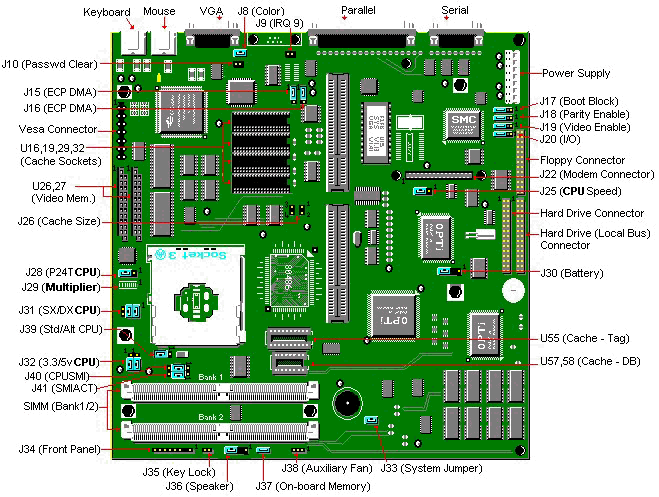
Packard Bell 450 M/Board

Specification
- Battery : 3.0V DC Lithium soldered on motherboard.
- BIOS : Phoenix v4.03 X1.1A
- Bus Architecture : ISA based system bus.
- Cache : Write Back: 8 KB Internal (Level 1) Cache External (Level 2).
- CPU : Intel 486 processor.
- Interfaces :
- 1 DB-25F Parallel.
- 1 RS232,DB-9M Serial.
- 1 15-pin HDF VGA.
- 1 PS/2 Mouse.
- 1 PS/2 Keyboard.
- RAM : 4 MB Standard on Motherboard 64 MB Maximum on Motherboard.
- Speaker : Piezoelectric soldered on motherboard.
- UART : Compatability Compatible with the 16C550 UART.
- Video : Built in Cirrus Logic 5428 or 5429.
Jumpers
| Jumper | Function | Setting | Description |
|---|---|---|---|
| J8 | Color/Mono select | Closed Open | * Colour Monochrome |
| J9 | Video IRQ enable | Closed Open | * Enabled Disabled |
| J10 | Password clear | Closed Open | Clear Password * Normal Operation |
| J11 | Onboard game port select | Closed Open | * Enabled Disabled |
| ** J15 / J16 | ECP DMA select | 1-2 2-3 | * DMA Channel 1 DMA Channel 2 |
| J17 | Boot Select | 1-2 2-3 | Boot Block * Normal |
| J18 | Parity Enable | 1-2 2-3 | Enabled * Disabled |
| J19 | Onboard VGA Enable | 1-2 2-3 | Disabled * Enabled |
| J20 | Onboard I/O Controller | 1-2 2-3 | Disabled * Enabled |
| J25 | CPU Speed select | 1-2 2-3 | 25MHz 33MHz |
| J26 | Cache size selection | Open 1-2, 3-4 | 0K 128K 512K |
| J28 | P24T or S-series reset control | 1-2 2-3 | * P24T S-series CPU Standard CPU (Do Not Change to add P24) |
| J29 | P24C Clock multiplier | 1-2 2-3 Open | Other Multiplier X2 Internal clock X3 Internal clock |
| J30 | Onboard battery enable | Open 3-4 | Use external battery * Use internal battery |
| J31 | SX processor selection | 1-2 3-4 5-6 | All except (SX) SX |
| J32 | J(3.3v) (CPU voltage) | 1-3 2-4 3-5 4-6 | 3.3V CPU * 5.0V CPU |
| J33 | LDEV bypass | Open Closed | Disabled Enabled |
| J36 | Onboard speaker enable | Open 3-4 | External speaker * Internal speaker |
| J37 | Onboard memory Disable | Open Closed | * Enabled Disabled |
* Indicates default value.
** J15 and J16 must match
Battery
Use a 3 volt lithium battery. Remove the jumpers on pins 3-4 of the J30 (Jbte) battery connector. The battery will connect to pins 1 and 4 (pin 1= +3 volts, pin 4= ground)
Cache Upgrade
The Cache and TAG RAM are either 28-pin for 128KB of cache, or 32-pin for 512KB of cache.
| J26 | |
|---|---|
| None | Open |
| 128k | Open |
| 512k | Closed |
CPU Upgrades
| Jumpers | J25 | J29 | J31 |
|---|---|---|---|
| CPU | Speed | Multiplier | SX/DX |
| 486SX25 | 1-2 | 1-2 | 5-6 |
| 486SX33 | 2-3 | 1-2 | 5-6 |
| 486SX/2-50 | 1-2 | 2-3 | 5-6 |
| 486DX-33 | 2-3 | 1-2 | 1-2 & 3-4 |
| 486DX/2-50 486-25 486DX/4-75 P24T-62MHz | 1-2 | 2-3 | 1-2 & 3-4 |
| 486DX/2-66 ODP486-33 P24T-83MHz | 2-3 | 2-3 | 1-2 & 3-4 |
| 486DX/4-100 | 2-3 | none | 1-2 & 3-4 |
- The motherboard DOES NOT support any 3.3 Volt CPUís, regardless of motherboard revision.
- The upgrade processor installs in the Zero Insertion Force (ZIF) socket at location U50.
- Jumper J29 is not available on all systems.
- If you wish to upgrade the processor with an Intel P24T (Pentium Overdrive), the Interposer is required. An Interposer can be obtained from Intel or from the dealer. Please note that the Interposer will disable the 2nd level cache.
- For the P24T-83, you may also need to update the BIOS to version 1.1a. The current BIOS version appears on the display immediately after starting up.
Memory Upgrades
- This motherboard does not accept EDO memory.
- SIMM speed must be 70 or 80ns. 60ns SIMMS will only work if the on-board memory is disabled.
- The SIMMS are 72-pin, non-parity (32 bit) because the motherboard design does not require parity checking. The parity jumper does not have to be changed.
- Use silver plated SIMMS.
- The board comes with 4MB soldered onto the motherboard (SMT), and will take 4/8/16/32 MB SIMMs up to a maximum of 64MB.
- When two 32 MB SIMMS are installed, the SMT memory needs to be disabled. This is done by jumping J37 (On Board Memory Disable).
Speaker
Use an 8 ohm, .5 watt computer speaker. Remove the jumper on pins 3-4 of the J36 (Jspk) connector. The Speaker will connect to pins 1 and 4. (pin 1= =5 volts, pin 4=speaker ground).
Video Memory Upgrade
- You can upgrade the video memory on your system from 1MB to 2MB by using 256Kx16 (Symmetrical, CAS line) DRAM ZIPís.
- You will need two of these to perform the upgrade.