 Acer File Extensions |
Apricot Diamond Motherboard
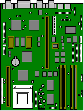
Cache SIMM Socket
If your computer came without any cache fitted you can install a 256Kb module of either of the following types:-
256KB Async Cache Module
256KB 55MHz Pipelined Sync
If you have a 75MHz motherboard it will not have a cache SIMM, due to the performance benefits of EDO RAM. If you upgrade the processor at a later date you may require a cache upgrade to improve performance further.
Video RAM
If your machine came with 1MB video RAM then it can be upgraded as follows (depending on your Video Card) -
GD5434 1MB to 2MB Video RAM Upgrade
GD5436 1MB to 2MB Video RAM Upgrade
If your machine came with 2MB already installed then it cannot be upgraded further.
RAM Configuration
The SIMM sockets are located at the front of the motherboard. Each pair of sockets can be fitted with SIMMs. SIMMs with capacities of 2, 4, 8, 16 or 32 Mbytes are supported, giving a maximum capacity of 128 Mbytes.
Socket Location
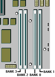
SIMMs must be fitted in pairs and the pair must be identical. The system does not require Parity checking (36-bit) SIMMs. Conventional 32-bit SIMMs with a refresh rate of 70ns is the specification. The newer Extended Data Output (EDO) type SIMMs are supported and will give enhanced performance.
Note: MS530 has only Banks 0 & 1 available for memory expansion.
Processor Upgrade
These are is the processor upgrades for MS530's and MS540's with the model number prefixes MK or MT.To use the tables below, select the processor you wish to upgrade to and confirm that the upgrade is possible. Then check additional requirements such as BIOS upgrades & processor speed jumper settings.
Warning
DO NOT alter these links unless you are upgrading the processor as it could lead to the destruction of the processor and/or other vital components on the board.
| MS530 (MK) &MS540 (MT) Processor upgrades | |
|---|---|
| Processor type and speed | Is it supported? |
| Pentium 120 | YES (set speed jumpers) |
| Pentium 133 | YES (set speed jumpers) |
| Pentium 150 | YES (set speed jumpers) |
| Pentium 166 | YES (set speed jumpers and upgrade BIOS) |
| Pentium 200 | YES (set speed jumpers and upgrade BIOS) |
| Pentium 166 MMX | NO (no support for full 2.8volt MMXprocessor) |
| Pentium 200 MMX | NO (no support for full 2.8volt MMXprocessor) |
| Pentium 233 MMX | NO (no support for full 2.8volt MMXprocessor) |
| Pentium Overdrive 166 MMX (BPODPMT66X166). Will run at 100mhz or 133Mhz. | YES (upgrade BIOS then set speed jumpers to 100mhz or 133mhz) |
| Pentium Overdrive 180 MMX (BPODPMT60X180). Will run at 75, 90, 120 & 150Mhz. | YES (upgrade BIOS then set speed jumpers to 75, 90, 120 or 133mhz) |
| Pentium Overdrive 200 MMX (BPODPMT66X200). Will run at 100, 133 & 166Mhz. | YES (upgrade BIOS then set speed jumpers to 100, 133 or 166mhz) |
| Processor and BUS clock | |||
|---|---|---|---|
| Processor Speed | PL17 | SW1, || = Link, : = No link | ISA (MHz) |
| Pentium P 75 | VRE | Pin 1 || || : : : : : : | 8.33 |
| P 90 | VRE | Pin 1 : || : : || : : : | 7.5 |
| P 100 | VRE | Pin 1 || : : : || : : : | 8.33 |
| P 120 | VRE | Pin 1 : || || : || : : : | 7.5 |
| P 133 | VRE | Pin 1 || : || : || : : : | 8.33 |
| P 150 | VRE | Pin 1 : || || || || : : : | 7.5 |
| P 166 | VRE | Pin 1 || : || || || : : : | 8.33 |
| P 200 | VRE | Pin 1 || : : || || : : : | 8.33 (5-07 BIOS or greater) |
BIOS Upgrade
For MK (MS530) and MT (MS540) model machines, the latest version of the BIOS is 5.09.
BIOS Installation Instructions
Once the BIOS update file has been downloaded & saved in your C:\WINDOWS\TEMP folder:
Click on START
Click on RUN
Type in c:\windows\temp\D509COMB.EXE
Press RETURN, then click on UNZIP (this will create three files in your C:\WINDOWS\TEMP folder).
Place a blank formatted disk into the floppy drive A:
Click on START
Click on RUN
Type C:\WINDOWS\TEMP\IMAGE 509BIOS.IMG A: /M /B
When the boot disk has been created, restart the computer and boot from the diskette.
From the menu press 1 to detect the type of video controller, and then press 2 or 3 to upgrade the BIOS for your type of video controller.
Jumper Settings
Internal speaker operation
Next to outer SIMM socket, default position link pins 4 and 5 gives audio output to the internal speaker in mono. Only to be removed in a system having internal stereo speakers.
| PL2 | Stereo: L Cable = 1,2. R Cable = 5,6 |
| Mono: Cable = 2,3. Jumper = 4,5 |
Internal 'audio' modem
Just along from the CD audio connection, default position if no internal modem is fitted, link pins 3 and 4. Remove only when fitting an internal modem supporting sound.
| PL4 | Modem absent = 3,4 |
| Modem present = no jumper |
BIOS reprogramme
These links are for special purposes. Only to be used for an official upgrade to the system BIOS. DO NOT move for any other reason.
| PL5 | Reserved. Do not change from 2,3 |
| PL6 | Flash Program. Enable = 1,2. Disable = 2,3 |
Floppy disk control mode
Next to floppy disk ribbon connector, default position link pins 3 and 4.
| PL13 | 2 mode = |  |
| 3 mode = |  |
Clear BIOS settings
Next to outer video upgrade socket, default position linkpins 1 and 2.Moving the link to pins 2 and 3 disconnects the battery from the BIOS memory, and will cause all the user settings to be lost. To be used with caution and only in the event of an access password being lost.
| PL21 | Normal = 1,2. Clear = 2,3. |
Video / VESA option
A single jumper may be the only one fitted, at the end nearest PL21.Only needs to be removed if fitting a new high feature 'plug-in' video card and serious problems are encountered. If taken out, it must be replaced if the extra video card is subsequently removed.
| PL22 | Video enabled, do not alter |
Sound Blaster Address
| IC12 | Near CD audio connector. Default position, link rear pins, sets the on-board Sound Blaster to address 220h. Removing the link changes the address to 240h |
PL24, PL28
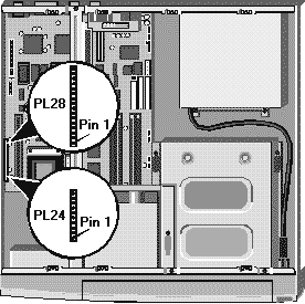
This range of pins is not exactly for jumpers, but is used to connect various features around the system case to the motherboard.
| PL24 | Pins | 1 to 4 | HDD active light |
|---|---|---|---|
| 5 to 9 | Keylock (not fitted) | ||
| 10 & 11 | System in 'power standby' light | ||
| 12 & 13 | System hardware reset (not fitted) | ||
| PL28 | Pins | 1 & 2 | System standby restore switch |
| 3 to 7 | Infrared controller | ||
| 8,9,10 | Fan, slow mode | ||
| 11,12,13 | Fan, full speed mode | ||
| 14 to 17 | Internal speaker (only when no audio fitted to motherboard) |
Rear Panel
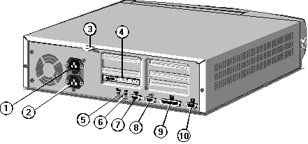
| 1 - AC Power Inlet | 5 - Keyboard Port | 9 - Parallel Port |
| 2 - AC Power Outlet | 6 - Mouse Port | 10 - Video Port |
| 3 - System Security Loop | 7 - Serial Port 1 | |
| 4 - Audio Ports | 8 - Serial Port 2 |
Expansion Slots
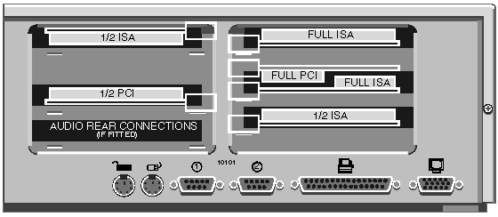
Clear BIOS Settings / CMOS Discharge
To clear the BIOS. you need to move jumper PL21, which is situated next to outer video upgrade socket.By default the jumper should be set to 1-2.
Moving the link to pins 2 and 3 disconnects the battery from the BIOS memory, and will cause all the user settings to be lost. To be used with caution and only in the event of an access password being lost.
| PL21 | Normal = 1, 2. Clear = 2, 3 |
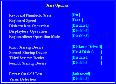
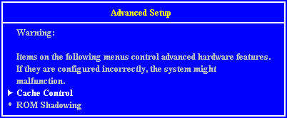
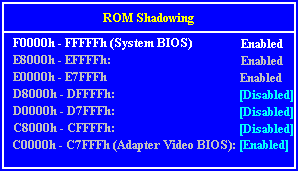
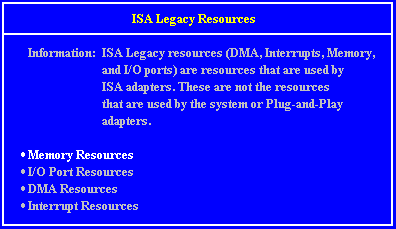
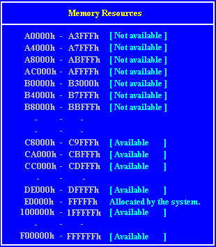
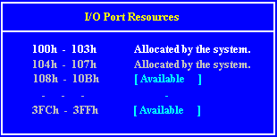
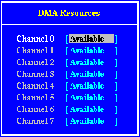
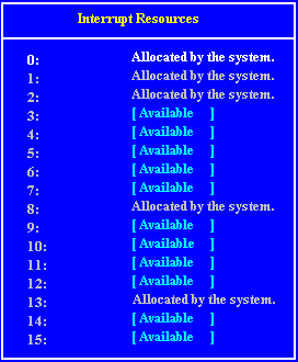
BIOS Screens
When this appears in the top right of the screen press the F1 on the keyboard and in a few seconds you will be presented with the BIOS setup screen see below)
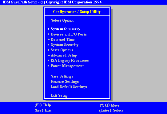
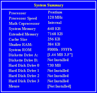
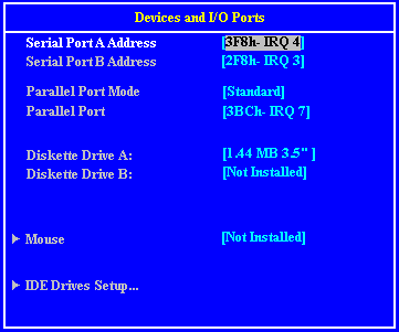
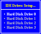


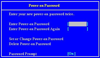
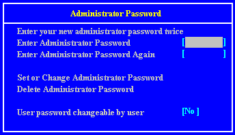

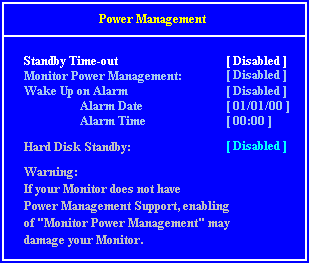

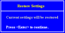

Interrupts, Memory & I/O Ports
Interrupts (IRQ)
| Interrupts | Default Function | Available ? |
|---|---|---|
| IRQ 0 | System timer | No |
| IRQ 1 | Keyboard | No |
| IRQ 2 | Cascade | No |
| IRQ 3 | Serial port 2 | Optionally |
| IRQ 4 | Serial port 1 | Optionally |
| IRQ 5 | Audio (if fitted) | Yes |
| IRQ 6 | Diskette controller | No |
| IRQ 7 | Parallel port | Optionally |
| IRQ 8 | Real time clock | No |
| IRQ 9 | Not used | Yes |
| IRQ 10 | Not used | Yes |
| IRQ 11 | Not used | Yes |
| IRQ 12 | Mouse | No |
| IRQ 13 | Co processor | No |
| IRQ 14 | Primary ATA/IDE interface | No |
| IRQ 15 | Secondary ATA/IDEinterface | No |
I/O Ports
| I/O ports (Hex) | Used by |
|---|---|
| 000 - 01F | DMA controller 1 |
| 020 - 021 | Interrupt controller 1 |
| 022 - 023 | ALI configuration port |
| 034, 038, 03C | Local bus ATA/IDE (alternate) |
| 040 - 05F | System timer |
| 060 - 06F | Keyboard controller |
| 070 - 07F | Real time clock,NMI mask |
| 080 - 09F | DMA page register |
| 0A0 - 0A1 | Interrupt controller 2 |
| 0B4, 0B8, 0BC | Local bus ATA/IDE (default) |
| 0C0 - 0DF | DMA controller 2 |
| 0F0, 0F1 | Math coprocessor busy (clear/reset) |
| 0F8 - 0FF | Math coprocessor |
| 1F0 - 1F7 | Hard disk drive controller |
| 200 - 207 | Game I/O |
| 278 - 27F | Parallel port 2 |
| 2B0 - 2DF | Alternate VGA |
| 2F8 - 2FF | Serial port 2 |
| 378 - 37F | Parallel port 1 |
| 3B0 - 3BF | Monochrome display and printer adapter |
| 3B4, 3B5, 3BA | Video subsystem |
| 3C0 - 3C5 | VGA |
| 3C6 - 3C9 | Video DAC |
| 3CA - 3DF | VGA |
| 3F0 - 3F7 | Diskette drive controller |
| 3F8 - 3FF | Serial port 1 |
Direct memory access (DMA) channel
| DMA | Default Function | Available ? |
|---|---|---|
| DMA 0 | Yes | |
| DMA 1 | 8-bit Audio | Optionally |
| DMA 2 | Diskette Controller | No |
| DMA 3 | Enhanced Capabilities Port | Optionally |
| DMA 4 | System | No |
| DMA 5 | 16-bit Audio | Optionally |
| DMA 6 | Yes | |
| DMA 7 | Yes |
Error Codes
| Code | Causes |
|---|---|
| 101 | Timer tick interrupt failure |
| 102 | Timer 2 test failure |
| 106 | Diskette controller failure |
| 110 | System Board Memory Parity interrupt |
| 114 | Option ROM checksum failure |
| 151 | Real time clock failure |
| 161 | Real time clock battery failure |
| 162 | CMOS RAM checksum failue |
| 162 | Invalid configuration information |
| 163 | Time of day not set -preboot |
| 164 | Memory size does not match CMOS |
| 175 | Bad EEPROM CRC #1 |
| 176 | System tampered |
| 177 | Bad PAP checksum |
| 178 | EEPROM is not functional |
| 183 | PAP Update Required |
| 184 | Bad POP checksum |
| 185 | Corrupted Boot Sequence |
| 186 | Hardware problem |
| 189 | Excessive password attempts |
| 201 | Base memory error |
| 229 | External cache failure |
| 303 | Keyboard controller failure |
| 301 | Keyboard failure |
| 301 | Keyboard clock line failure |
| 301 | Keyboard data line failure |
| 301 | Keyboard stuck key failure |
| 604 | Diskette drive 0 failure |
| 604 | Diskette drive 1 failure |
| 605 | Diskette unlocked problem |
| 662 | Diskette drive configuration |
| 762 | Coprocessor configuration |
| 1762 | Hard disk configuration |
| 1780 | Fixed disk 0 failure |
| 1781 | Fixed disk 1 failure |
| 1782 | Fixed disk 2 failure |
| 1783 | Fixed disk 3 failure |
| 1800 | No more IRQ available |
| 1801 | No more room for option ROM |
| 1802 | No more I/O space available |
| 1803 | No more memory (< 1MB) available |
| 1804 | No more memory (> 1MB) available |
| 1805 | Checksum error or 0 size option ROM |
| 1962 | No bootable device |
| 2400 | Display adapter failed; using alternate |
| 2462 | Video configuration |
| 5962 | IDE CD-ROM configuration |
| 8603 | Pointer device has been removed |