 Acer File Extensions |
Advent 8270 PC
| Motherboard | Gigabyte GA-686LX |
| Hard Drive | 8GB |
| CD Drive | Matshita CD-ROM CR-589 |
| Floppy Drive | Floppy disk drive fitted |
| Video Card | ATI 3D Rage Pro |
| Sound Card | Creative Ensoniq |
| Modem | US Robotics 56k Winmodem |
| Ports (rear) | 1x PS/2 Keyboard 1x PS/2 Mouse 2x USB 1x Parallel 2x Serial 1x VGA 1x Headphone 1x Microphone |
Information on known issues with the 8000 series recovery discs can be found on this page.
Motherboard Information
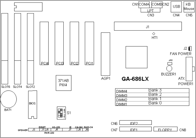
Note - There are two versions of the GA-686LX motherboard, the only difference being the number of memory slots. The GA-686LX3 has 3 slots (max 768MB) while the GA-686LX4 has 4 slots (max 1GB)

| Ref No | Descriptions |
|---|---|
| CN1 | For Serial port1 (COM A). |
| CN2 | For Serial port2 (COM B). |
| CN3 | For LPT port. |
| CN4 | USB port. |
| CN5 | For Keyboard I/O port. |
| CN5 | For PS/2 Mouse port. |
| CN6 | For Secondary IDE port. |
| CN7 | For Primary IDE port. |
| CN8 | For Floppy port |
| POWER1: | ATX POWER connector |
| J1 | Slot1 For Pentium II processor installed. |
| J2 | CPU cooling FAN Power Connector |
| J3 | SPEAKER Connector |
| J4 | RESET Switch |
| J5 | POWER ON LED (PW-LED) |
| J6 | Hard Disk active LED (HD-LED) |
| J7 | INFRARED Connector (IR) -- Function Option |
| J8 | GN-SW
|
| J9 | Soft Power Switch
|
| J10 | Green LED
|
Specification
- BIOS : Licensed AWARD BIOS. 256KB FLASH EEPROM. Supports Plug & Play, DMI, ACPI Function.
- Cache Memory :
- 32 KB 1st cache memory included in CPU.
- 256KB/512 KB 2nd cache in CPU.
- Support DIB speed mode for L2 Cache.
- 1 66MHz / 133MHz AGP bus.
- Dimension : ATX Form Factor, 4 layers PCB.
- DRAM Memory :
- 4 banks 168 pins DIMM module sockets on board.
- Use 8 / 16 / 32 / 64 / 128 / 256 MB 60~70 ns DIMM module DRAM.
- 8 ~ 1 GB DRAM size.
- Support 3.3V SDRAM / EDO type DRAM.
- Support ECC or Non-ECC type DRAM.
- I/O Bus Slots :
- 4 33MHz Master / Slave PCI-BUS.
- 3 8MHz 16 bits ISA BUS.
- I/O Ports :
- 2 16550 COM ports. (Using IRQ4, 3)
- 1 EPP/ECP LPT port. (Using IRQ7 or 5 and DMA3 or 1)
- 1 1.44/2.88 MB Floppy port. (Using DMA2 & IRQ6)
- 2 USB ports.
- PS/2 Mouse. (Using IRQ 12)
- PS/2 Keyboard. (Using IRQ 1)
- IDE Ports :
- 2 Ultra DMA/33 Bus Master IDE channels on board.(Using IRQ14,15)
- Back ward Support Mode 3,4 IDE & ATAPI CD - ROM.
- Power Management :
- Suspend mode support.
- Green switch & LED support.
- IDE & Display power down support.
- Monitor all IRQ / DMA / Display / I/O events.
- Processor : Pentium II processor 233 – 633 MHz. 242 pins 66MHz slot1 on board.
- Protection :
- Onboard Buzzer Alarm when detect "CPU FAN Failure" or "CPU Overheat".
- Automatically slow down CPU speed when "CPU FAN Failure" or "CPU Overheat".
- Intel LDCM support.
- H/W monitor power status (5V, 12V, CPU voltage & CMOS battery voltage).
- Speed :
- 66 MHz system speed.
- 66 MHz AGP bus speed. (133MHz 2*mode).
- 33 MHz PCI-Bus speed.
- 8 MHz AT bus speed.
CPU Upgrade
The system's speed is fixed to 66.6MHz. The user can change the DIP SWITCH (S1) selection to set up the CPU speed for 233 - 633MHz processor. The CPU speed must match with the frequency RATIO. It will cause system hanging up if the frequency RATIO is higher than CPU's.
| S1: CPU INT. / EXT. FREQ. Ratio | ||||||
|---|---|---|---|---|---|---|
| 1 | 2 | 3 | 4 | CLK Ratio | EXT.CLK. MHz | CPU Type |
| OFF | ON | OFF | OFF | X3 | 66 | Pentium II 200 MHz |
| ON | ON | OFF | OFF | X3.5 | 66 | Pentium II 233 MHz |
| OFF | OFF | ON | OFF | X4 | 66 | Pentium II 266 MHz |
| ON | OFF | ON | OFF | X4.5 | 66 | Pentium II 300 MHz |
| OFF | ON | ON | OFF | X5 | 66 | Pentium II 333 MHz |
| ON | ON | ON | OFF | X5.5 | 66 | Pentium II 366 MHz |
Memory Upgrade
The mainboard can be installed with 4 / 8 / 16 / 32 / 64 / 128 / 256 MB 168 pins DIMM module DRAM, and the DRAM speed must be 50 or 60 ns for EDO & 67~100 MHz for SDRAM. The DRAM memory system on mainboard consists of bank 0, 1, 2 & bank 3. Each bank consists of 3 PCS 168 pins DIMM module DRAM.
Because the 168 pins DIMM module is 64 bits width, using 1 PCS which can match a 64 bits system. The total memory size is 8 MB ~ 1 GB EDO / 512MB SDRAM. The DRAM installation position refer to Figure 3.1, and notice the Pin 1 of DIMM module must match with the Pin 1 of DIMM socket. Insert the DRAM DIMM module into the DIMM socket at Vertical angle. If there is a wrong direction of Pin 1, the DRAM DIMM module couldn't be inserted into socket completely.