Acer File Extensions |
Advent 7006 Laptop
Specification
| CPU | Intel Pentium 4 1.8GHz |
| BIOS | Insyde BIOS. Press F2 to enter |
| Chipset | Mobile Intel 845 |
| Memory | 512MB 144-pin PC133 DIMM SDRAM (2 memory slots. Max 1GB) |
| Hard Drive | 30GB HITACHI DK23CA-30 |
| CD Drive | Matshita UJDA720 DVD-ROM / CD-R/RW Combo Drive * |
| Screen | 14.1" TFT (Native Res.1024x768) |
| Video Card | ATI Mobility M6 16MB |
| Sound Card | Avance AC'97 |
| Modem | HSP 56 MR-8170 |
| LAN | RealTek RTL 8139/810X 10/100 Fast Ethernet |
| PC Card | 1x Type I/II |
| Ports | 1x Parallel 1x IEEE1394 (FireWire) 1x VGA 1x S-Video (TV-Out) 2x USB 1x LAN 1x Modem 1x Microphone 1x Headphone 1x IR 1x Kensington Lock |
| Made by | Hi Grade 8170 Mitac 8170 |
* May have a Toshiba DVD-ROM SD-R2102 drive fitted instead.
Drivers
Your laptop should have been supplied with a "Utility and Driver CD" which contains a backup copy of all the drivers.
The 7006 is basically a rebadged Mitac 8170 (you should see 8170 printed on the underside of the laptop), the user manual is available in PDF format here - Download User Manual.
Upgrading the Memory
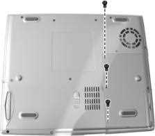
- Carefully put the notebook upside down
- Remove the three screws to access the SO-DIMM socket
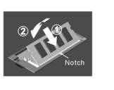
- To install the SO-DIMM, match the SO-DIMM's notched part with the socket's projected part and firmly insert the SO-DIMM into the socket at 20-degree angle (1). Then push down until the retaining clips lock the SO-DIMM into position (2)
Accessing Other Internal Components
Installing a Processor
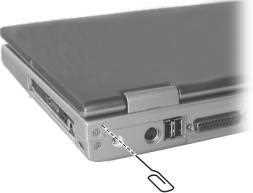
- Insert a small rod, such as a straightened paper clip, into the eject hole near the power connector of the notebook
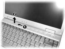
- Push the rod firmly and slide the LED panel to the left (1) Lift up the LED panel from the left side (2)
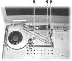
- Remove the screw locking the keyboard, then slightly lift up the keyboard to access the CPU compartment
- Remove the three screws locking the heatsink and disconnect the fan’s power cord from the system board, then lift up the heatsink
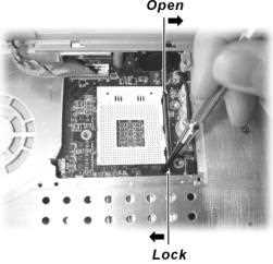
- Use a flat screwdriver to push the lever to the right. Then lift up the lever to the vertical position
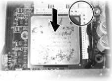
- Align the arrowhead corner of the CPU with the beveled corner of the socket, as shown below, and insert the CPU pins into the holes. Note: Make sure that the processor fits properly into the socket, NEVER use force as this may damage the pins
- Connect the fan’s power cord to the system board, then fit the heatsink onto the top of the CPU and secure with three screws. NOTE: Make sure that the thermal pad under the fan is not damaged, if it is damaged then replace with a new pad
- Replace the keyboard and secure with the screw. Then replace the LED panel
Replacing the Battery Pack
- Carefully put the notebook upside down
- Slide the release lever to the “unlock” position (1), then slide and hold the release lever outward and pull the battery pack out of the compartment (2)
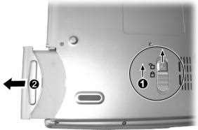
- To replace the old battery with a new one, insert the battery pack into the compartment. Then slide the release lever to the “lock” position
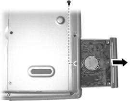
Replacing the HDD Module
- Carefully put the notebook upside down
- Remove one screw and pull the HDD module out of the compartment
- Remove the six screws to separate the hard disk drive from the metal shield.
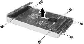
- To install a new hard disk drive, place it in the metal shield and tighten the six screws
- Slide the HDD module into the compartment and secure with one screw
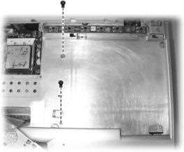
Replacing the CD/DVD-ROM Drive
- Remove the LED panel and keyboard (see the processor section above)
- Remove two screws locking the CD/DVD-ROM drive
- Use the screwdriver to push the medal pad to the right and the CD/DVD-ROM drive will pop out slightly. Hold the CD/DVD-ROM drive and slide it outward carefully
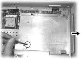
- To install a new CD/DVD-ROM drive, push it into the compartment, and the connector on the system board will automatically plug into the rear side of the drive
- Replace two screws locking the CD/DVD-ROM drive
- Replace the keyboard and LED panel
Function Keys
Fn + F5 - Toggle the display between LCD, CRT, LCD+CRT, TV, and TV+CRT *
Fn + F6 - Increase brightness
Fn + F7 - Decrease brightness
Fn + F10 - Turns Battery Warning Beep on or off
Fn + F11 - Switches LCD on and off
Fn + F12 - Sleep button (settings controlled via Windows’Power Management)
* Note - If the display mode is set to 256 colors or lower, or in DOS mode, there will be only two modes for selecting: CRT only and LCD & CRT.
In the Box
Disks Supplied
- Advent 7006 recovery CD
- Notebook driver CD
- Intervideo WinDVD 2000 CD (serial number on the rear of the CD sleeve)
Items Supplied
- Advent 7006 notebook
- Mains power adapter
- Mains power cable
- UK modem cable
- BT connector
Documentation Supplied
- User manual
- Advent installation and troubleshooting guide
- "Windows XP start here" guide
- Freeserve leaflet
Recovery
A Bootable Recovery CD is supplied with these machines. To recover the system:-
- Insert CD into the drive.
- Reboot the PC.
- Press "R" when prompted to boot from the CD.
- After a few minutes the recovery screen will be displayed. By default "Non Destructive Recovery" is selected. Press Next to continue. This does NOT delete user files.
- If you wish to format the drive select Advanced Options from the main screen. Select "System Recovery - Quick Format" and click "Next". Note: By choosing this option you will lose all data on the notebook.
- You will now be reminded that System Restore can be used to attempt to remedy any problems they may have. Click YES to continue.
- Recovery now begins and takes approximately 45 minutes.
- Once complete you will be prompted to remove the CD and restart the notebook.
Driver CD
The notebook is supplied with a Utility CD. This can be used to restore corrupt drivers.
- Ensure Windows XP is running. Insert the CD into the drive.
- The CD will autorun and display a menu with the following options:
- Device Driver
- Readme
- Release Notes
- Browse CD
- Exit
- Click "Device Driver" to begin. The message "The drivers for your system will now be installed. Do you wish to continue?" Click YES.
- The program will now install files and restart Windows.
- When Windows restarts the individual drivers are loaded automatically. You may receive an error message for each driver as they are not digitally signed. Click "Continue Anyway" to carry on.
- Once the drivers are installed Windows will restart one last time.
FAQ
Realtek 8139 Network Card Not Connecting
Some machines fitted with a network card based on the Realtek 8139 chip will fail to send and receive data correctly. This can happen if the autodetect feature of the card is not detecting the connection properly. To get round this the connection speed of the card must be set manually
- Right-click upon the My Computer icon and select Properties.
- Select the Hardware tab and click on the Device Manager button.
- Click on the + next to Network Adapters.
- Select the entry for Realtek 8139 from the list and double click upon it.
- Select the Advanced tab.
- Select the entry for Link Speed / Duplex Mode.
- Change the Value setting from Auto to one that is appropriate for the connection (often 100 Full for a connection directly to another PC and 10 Full for a broadband connection).