 Acer File Extensions |
Acer V55LA-2 Motherboard
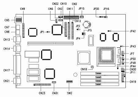
Jumper and Connector Layout

CPU Jumper Settings
| SW2 Settings | ||||||||
|---|---|---|---|---|---|---|---|---|
| CPU Freq | Host Bus Freq. | 1 | 2 | 3 | 4 | JP7 | JP43 | JP44 |
| Intel P54C P166 | 66 | OFF | ON | ON | ON | Closed | 2-3 | 2-3 |
| Intel P54C P200 | 66 | OFF | ON | OFF | ON | Closed | 2-3 | 2-3 |
| Intel P55C P150 | 60 | ON | OFF | ON | ON | Open | 2-3 | 2-3 |
| Intel P55C P166 | 66 | OFF | ON | ON | ON | Open | 2-3 | 2-3 |
| Intel P55C P200 | 66 | OFF | ON | OFF | ON | Open | 2-3 | 2-3 |
| Intel P55C P233 | 66 | OFF | ON | OFF | OFF | Open | 2-3 | 2-3 |
| AMD K6 PR166 | 66 | OFF | ON | ON | ON | Open | 2-3 | 1-2 |
| AMD K6 PR200 | 66 | OFF | ON | OFF | ON | Open | 2-3 | 1-2 |
| AMD K6 PR233 | 66 | OFF | ON | OFF | OFF | Open | 2-3 | 1-2 |
SW2 Settings
| Switch | Setting | Function |
|---|---|---|
| Sound Feature Switch 5 | ON OFF | Onboard sound chip disabled Onboard sound chip enabled |
| Password Security Switch 6 | ON OFF | Password bypass Password check |
Jumper Settings
| Jumper | Setting | Function |
|---|---|---|
| JP1 BIOS Type | 1-2 2-3 | For models with Acer BIOS For models with OEM BIOS |
| JP2 LED Function | 1-2 2-3 | LED for IDE and FDD LED for IDE only |
| JP3, JP4 Second-level Cache | 1-2, 1-2 1-2, 2-3 2-3, 2-3 | 256 KB 512 KB 1 MB |
| JP7 Regulator | Closed Open | For single-voltage CPUs (P54C, K5, M1) For dual-voltage CPUs (P55C, K6, M2) |
| JP11 SMM/Reset Switch | 1-2 2-3 | CN19 pins 19-20 support SMM switch Reserved |
| JP16 Software Shutdown | 1-2 2-3 | UPS enabled UPS disabled |
| CPU Voltage JP43 (for I/O) JP44 (for core) | 1-2 2-3 1-2 | 3.5V 3.3V 3.2V 2.8V |
Connector Functions
| Connector | Function |
|---|---|
| CN1 | Feature connector for multimedia or Ethernet solution |
| CN2 | CD-audio line-in connector |
| CN3 | Power connector |
| CN5 | USB Connector |
| CN6 | WaveTable connector |
| CN7 | PS/2 keyboard connector |
| CN8 | PS/2 mouse connector |
| CN9 | Audio I/O board connector |
| CN10 | Diskette drive connector |
| CN11 | IDE connector 2 |
| CN12 | IDE connector 1 |
| CN13 | Serial port 1 |
| CN14 | Serial port 2 |
| CN17 | Parallel port |
| CN18 | CPU fan connector |
| CN19 | Multifunction connector |
| CN21 | Video port |
| CN22 | Fax/modem connector |
| CN23 | ATI multimedia connector (AMC) |
| CN31 | Internal line-in connector |
| JP10* | Hard disk and diskette drive LED connector |
| JP14* | Power-on switch connector (pins 1-2) |
| JP15 | Standby power connector |
| JP30 | External battery connector |
| JP48** | Hard disk and message LED (pins 1-3-5) Power LED (pins 2-4-6) |
| JP30 | Power-on switch connector** |
* For generic version system board only.
** For Aspire version system board only.
Memory Upgrade
The system memory is upgradable to a maximum of 128MB via 72 pin SIMM sockets on board. These SIMM sockets accept 32MB, 60ns-70ns fast-page or EDO-type DRAM modules in capacities of 4-, 8-, 16-, and 32MB. Important: Do not mix EDO and fast-page mode DRAM in one configuration. Install only the same type of SIMMS in a bank.
BIOS
How do I enter the BIOS Setup Utility?
You can access the BIOS Setup Utility by pressing CTRL+ALT+ESC as the system is booting. At the bottom of the second start up screen you should see "To enter setup, press CTRL_ALT_ESC".
Note: If the system displays the Acer Splash Screen, once you hear the beep, you should begin pressing CTRL+ALT+ESC.You may need to press CTRL+ALT+ESC continuously until you access the BIOS setup screen.
Why do the USB ports on my Acer Aspire system not work?
Your Aspire system was produced during the very early stages of USB. We were ahead of the technology and installed USB ports in anticipation of USB standards being released. However those standards, and the support for USB was not available at the time your system was released. Therefore, the USB ports do not function and will not support USB devices.