 Acer File Extensions |
Acer V65LA Motherboard
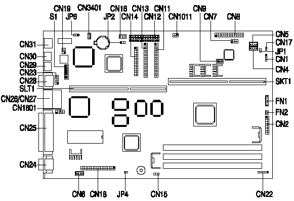
Jumper and Connector Layout

Note - The blackened pin of a jumper represents pin 1.
Specification
The V65LA system has the following features -
- for an Intel Pentium II 233/266/300/333MHz.
- Three 168-pin DIMM sockets that support 8/16/32/64/128-MB 10/12ns SDRAM DIMMs. Maximum : 384MB
- 512K cache in PII processor module, not upgradeable.
- 256K BIOS which is APM and Year 2000 compliant.
- Two Enhanced IDE interfaces supporting a total of four devices including UltraDMA hard drives and ATAPI CDROMs.
- External ports -
- PS/2 keyboard and mouse ports.
- One high-speed (NS16C550 compatible) serial port.
- One ECP/EPP high-speed parallel port.
- Two Universal Serial Bus ports.
- Onboard chipsets -
- Intel (Triton) 440LX with integrated E-IDE controller.
- SMC 37C93x I/O controller.
- Plug and Play support.
- Power management features (device standby, global standby).
- Universal Serial Bus support.
- Advanced Graphics Port (AGP) support.
- Video Memory - 2MB SGRAM or 4MB SGRAM (dependant on the system model), not upgradeable.
How do I access my BIOS?
Resolution: You can access the BIOS by pressing CTRL+ALT+ESC as the system is booting. At the bottom of the second start up screen you should see "To enter setup, press CTRL_ALT_ESC".
Note: If the system displays the Acer Splash Screen, once you hear the beep, you should begin pressing CTRL+ALT+ESC. You may need to press CTRL+ALT+ESC continuously until you access the BIOS setup screen.
How to enable the USB Port
- Enter the BIOS Utility Setup by pressing Ctrl+Alt+Esc during the boot-up process, but before the Operating System loads.
- When the BIOS Utility Menu appears press F8.
- Select Advanced Configuration.
- Select Onboard Peripheral Configuration.
- Ensure the USB settings are as follows:
- USB Host Controller ------------ [Enabled ]
- USB Legacy Mode -------------- [Disabled]
- Press Esc three times and select Yes to save changes and exit.
Caution: Changes made in the BIOS Setup Utility influence the entire system and are made to achieve specific effects. Varying from this procedure or making additional changes is not recommended.
How can I disable the on-board LAN?
The V65LA Main Board has an on-board Intel 82558 LAN chip. There are no BIOS settings or jumpers on the Main Board to disable this function. The only way to disable this function is through the Device Manager in System Properties. To disable the on-board LAN please use the following steps:
- Right click on My Computer and select Properties.
- Select the Device Manager tab.
- Click on the plus mark in front of Network adapters.
- Right click on the drop down, Intel 82558 adapter and select properties.
- At the bottom of the General tab, select Disable this hardware profile.
- Close the open application windows and restart system.
Note: Do not delete the on-board LAN adapter. If the on-board LAN adapter is deleted the computer will automatically reinstall it the next time the system boots.
Switch settings
| Core/Bus Frequency Ratio | SW5 | SW6 | SW7 | SW8 |
|---|---|---|---|---|
| 2 | On | On | On | On |
| 4 | Off | On | On | On |
| 7/2 | On | Off | Off | On |
| 9/2 | Off | On | Off | On |
| Reserved | Off | Off | Off | Off |
| Switch | Setting | Function |
|---|---|---|
| SW1 | On Off | 60 MHz 66 MHz* |
| SW2 | On Off | Bypass Password* Check Password |
| SW3 | On Off | OEM BIOS Acer BIOS* |
Connector Functions
| Connector | Function |
|---|---|
| CN1 | HDD LED connector |
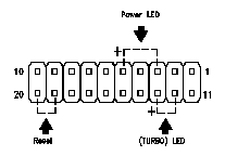
| CN2 | Multifunction connector (see Figure 1-5) |
| CN4 | Line-in connector |
| CN5 | CD-in connector |
| CN11 | Primary IDE Connector |
| CN12 | Power Connector |
| CN13 | Secondary IDE Connector |
| CN14 | Floppy Connector |
| CN15 | Modem Ring Connector |
| CN16 | Standby Power Connector |
| CN17 | Power SW Connector |
| CN18 | ATI/AMC connector |
| CN19 | LAN (ACT/Speed/LI) LED connector |
| CN22 | IRDA Board Connector |
| CN23 | USB interface |
| CN25 | Parallel port |
| CN26/CN27 | COM2/USB port |
| CN28 | COM1 port |
| CN29 | PS/2 mouse port |
| CN30 | PS/2 keyboard port |
| CN31 | Ethernet port |
| CN1011 | Appears-off connector |
| CN3401 | Wake on LAN (WOL) Connector |
| FN1 | CPU Fan Connector (5 pin) |
| FN2 | CPU Fan Connector (3 pin) |
| JP2 | Reserved for 935APM (default: 2-3) |
| The multifunction connector CN16 accommodates the front panel connectors for LEDs, reset, and turbo. Figure below shows the pin assignments for each connector. |
 |