 Acer File Extensions |
Acer V59LA Motherboard
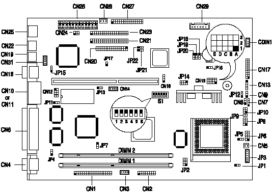
Jumper and Connector Layout

Note - The blackened pin of a jumper represents pin 1.
Jumper Settings
| Jumper | Setting | Function | ||||||||||||||||||||||||||||||||||||||||||||||||||||||||||||||||||||||||||||||||||||||||||||||||
|---|---|---|---|---|---|---|---|---|---|---|---|---|---|---|---|---|---|---|---|---|---|---|---|---|---|---|---|---|---|---|---|---|---|---|---|---|---|---|---|---|---|---|---|---|---|---|---|---|---|---|---|---|---|---|---|---|---|---|---|---|---|---|---|---|---|---|---|---|---|---|---|---|---|---|---|---|---|---|---|---|---|---|---|---|---|---|---|---|---|---|---|---|---|---|---|---|---|---|
| CN15 |
|
| ||||||||||||||||||||||||||||||||||||||||||||||||||||||||||||||||||||||||||||||||||||||||||||||||
| JP1, S1 |
|
| ||||||||||||||||||||||||||||||||||||||||||||||||||||||||||||||||||||||||||||||||||||||||||||||||
| JP2, JP14 | Closed, Open Open, Closed | CPU Voltage Type Selection Single voltage type CPU Dual voltage type CPU | ||||||||||||||||||||||||||||||||||||||||||||||||||||||||||||||||||||||||||||||||||||||||||||||||
| JP4 | 1-2* 2-3 | Video Interrupt Enabled Disabled | ||||||||||||||||||||||||||||||||||||||||||||||||||||||||||||||||||||||||||||||||||||||||||||||||
| JP5 | 1-2 2-3* | H/W Mon (CPU I/O Voltage) 3.52V 3.3V | ||||||||||||||||||||||||||||||||||||||||||||||||||||||||||||||||||||||||||||||||||||||||||||||||
| JP6 | 1-2 3-4 5-6 7-8 9-10 | H/W Mon (CPU Core Voltage) 2.8V 2.9V 3.2V 2.1V / 2.2V 1.8V | ||||||||||||||||||||||||||||||||||||||||||||||||||||||||||||||||||||||||||||||||||||||||||||||||
| JP7 | 1-2 2-3* | VGA Function Disabled Enabled | ||||||||||||||||||||||||||||||||||||||||||||||||||||||||||||||||||||||||||||||||||||||||||||||||
| JP8 | 1-3 2-4-6 7-8 | Multi Function Connector HDD LED Power LED / suspend LED Power switch button | ||||||||||||||||||||||||||||||||||||||||||||||||||||||||||||||||||||||||||||||||||||||||||||||||
| JP10 | 2-4 1-3-5 | LED Connector Power LED HDD LED | ||||||||||||||||||||||||||||||||||||||||||||||||||||||||||||||||||||||||||||||||||||||||||||||||
| JP11 | 1-2 2-3* | Flash ROM Type Selection 12V Flash ROM for MX brand 5V EPROM for SST and ATMEL brands | ||||||||||||||||||||||||||||||||||||||||||||||||||||||||||||||||||||||||||||||||||||||||||||||||
| JP12 | 1-2* 2-3 | CN9 Function Control Software shutdown switch Reset switch | ||||||||||||||||||||||||||||||||||||||||||||||||||||||||||||||||||||||||||||||||||||||||||||||||
| JP13 | 1-2* 2-3 | Upgrade BIOS by Boot Block Disabled Enabled | ||||||||||||||||||||||||||||||||||||||||||||||||||||||||||||||||||||||||||||||||||||||||||||||||
| JP15 | 1-2* 2-3 | LAN Function Enabled Disabled | ||||||||||||||||||||||||||||||||||||||||||||||||||||||||||||||||||||||||||||||||||||||||||||||||
| JP16 | 1-2* 2-3 | UPS Function Enabled Disabled | ||||||||||||||||||||||||||||||||||||||||||||||||||||||||||||||||||||||||||||||||||||||||||||||||
| JP18, JP19, JP20 | 1-2, 1-2, 1-2 2-3, 1-2, 1-2 1-2, 2-3, 2-3 2-3, 1-2, 2-3 | Host Bus / PCI Bus Frequency 66MHz / 33MHz 60MHz / 30MHz 75MHz / 30MHz 83.3MHz / 33MHz | ||||||||||||||||||||||||||||||||||||||||||||||||||||||||||||||||||||||||||||||||||||||||||||||||
| JP21 | 1-2 2-3* | BIOS Logo Control Check Bypass | ||||||||||||||||||||||||||||||||||||||||||||||||||||||||||||||||||||||||||||||||||||||||||||||||
| JP22 | 1-2 2-3* | Password Control Check Bypass | ||||||||||||||||||||||||||||||||||||||||||||||||||||||||||||||||||||||||||||||||||||||||||||||||
| S1 |
|
| ||||||||||||||||||||||||||||||||||||||||||||||||||||||||||||||||||||||||||||||||||||||||||||||||
| S1 | Switch 6 On Off* | Audio Function Control Disabled Enabled | ||||||||||||||||||||||||||||||||||||||||||||||||||||||||||||||||||||||||||||||||||||||||||||||||
Onboard Connectors
| Connector | Function |
|---|---|
| CDIN1 | CD-ROM audio-in connector |
| CN1 | AMC connector |
| CN2 CN17 | Front panel video-in Front panel joystick/earphone/speaker/line-in connector These two connectors are used to connect a front I/O board which has video capture functions and transfers joystick, earphone, speaker, and line-in signals capabilities. |
| CN3 | TV audio line-in |
| CN4 | VGA connector |
| CN5 | Normal fan connector |
| CN6 | Parallel port connector |
| CN7 | System speaker (buzzer) connector |
| CN8 | Power LED |
| CN9 | Reset or software shutdown switch connector (Selected by JP12) |
| CN12 | USB connector |
| CN10 or CN11 | Either COM2 or USB connector |
| CN13 | Volume up/down/mute connector (reserved) |
| CN14 | Wake-on LAN connector, connect to LAN adapter card. |
| CN15 | CPU voltage select jumper connector |
| CN16 | Modem ring-in wake up connector |
| CN18 | COM1 connector |
| CN19 | PS/2 mouse connector |
| CN20 | Floppy drive connector |
| CN21 | 1st IDE channel connector |
| CN22 | PS/2 keyboard connector |
| CN23 | 2nd IDE channel connector |
| CN24 | LAN status LED connector |
| CN25 | RJ45 (LAN) jack |
| CN26 | System power connector |
| CN27 | Audio I/O interface connector |
| CN28 | System standby power connector |
| CN29 | Fax/Modem line-in/speak-out connector |
| CN31 | IrDA connector (reserved) |
| JP3 | Hardware Monitoring fan connector |
| JP9 | Power switch button |
| JP17 | LAN status LED connector |
| JP25 | System buzzer (option) |
Memory
The system memory is upgradable to a maximum of 256MB via two 168-pin DIMM sockets on board. These DIMM sockets accept 128MB, 3.3V, 10ns Synchronous DRAM modules in capacities of 8-, 16-, 32-, 64-, and 128-MB.
Known Issues
Setting Up USB in Windows 95
When going into the BIOS to enable both USB function and USB legacy mode, system boots Okay. Windows 95 detects the ports and attempts to install the USB drivers and then attempts to install the Standard OpenHCD USB Host Controller driver, but cannot find the OPENHCL.SYS driver. The USB Supplement that is a part of the preload incorrectly copies the needed OPENHCI.SYS driver to the \WINDOWS\SYSTEM directory instead, thus necessitating that the installer be pointed to that directory.
Resolution: Edit memory range to FFFDF000-FFFDFFFF to remove conflicting addresses. The USB Root Hub will then properly install with no conflicts. To do this from the desktop:
- Click Start, then on Run.
- Type in SYSEDIT and click on OK.
- Go to the file called CONFIG.SYS and locate the line starting with DEVICE=C:\WINDOWS\EMM386.EXE...".
- Place your cursor at the end of this line. Press the spacebar and then type X=FFFDF000-FFFDFFFF.
- Click on File, the save.
- Close SYSEDIT.
- Shutdown Windows and reboot the computer.
Cause: The default setup chooses memory range 00000000-00000FFF, but that conflicts with the System Board Extension for the PnP BIOS.
How do you access the BIOS?
The BIOS can be accessed by pressing CTRL+ALT+ESC as the system is booting. At the bottom of the second start up screen you should see "To enter setup, press CTRL_ALT_ESC".
Note: If the system displays the Acer Splash Screen, once you hear the beep, you should begin pressing CTRL+ALT+ESC. You may need to press CTRL+ALT+ESC continuously until you access the BIOS setup screen.