Acer File Extensions |
Acer V58LA Motherboard
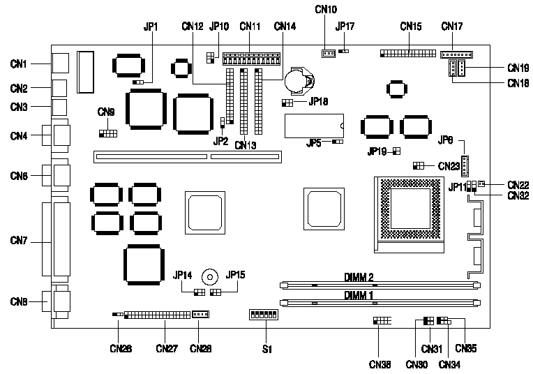
Jumper and Connector Layout
Note - The blackened pin of a jumper represents pin 1.
Specification
The V58LA system has the following features -- ZIF socket 7 for an Intel Pentium 90/100/120/133/150/166/200/233MHz including MMX, Cyrix/IBM M1/M2 and AMD K5/K6.
- Two 168-pin DIMM sockets that support 8/16/32/64/128-MB 10/12ns 3.3V SDRAM modules. Upgradable to a maximum of 256 MB
- 256K pipeline-burst second level cache onboard which is not upgradeable.
- 1-MB video memory.
- 256K BIOS which is APM and Year 2000 compliant.
- Two Enhanced IDE interfaces supporting a total of four devices including UltraDMA hard drives and ATAPI CDROMs.
- External ports -
- PS/2 keyboard and mouse ports.
- One high-speed (NS16C550 compatible) serial port.
- One ECP/EPP high-speed parallel port.
- VGA port.
- Two universal serial bus ports.
- Onboard chipsets -
- Aladdin IV system chipset (equivalent to Intel Triton TX) with integrated E-IDE.
- ATI Mach64 GT(Rage II) PCI graphics adapter.
- SMC 37C93x I/O controller.
- Plug and Play support.
- Power management features (device standby, global standby).
How do I access my BIOS?
You can access the BIOS by pressing CTRL+ALT+ESC as the system is booting. At the bottom of the second start up screen you should see "To enter setup, press CTRL_ALT_ESC".
Note: If the system displays the Acer Splash Screen, once you hear the beep, you should begin pressing CTRL+ALT+ESC. You may need to press CTRL+ALT+ESC continuously until you access the BIOS setup screen.
How do I enable the USB port?
The USB function is enabled in the BIOS by pressing Ctrl+Alt+Esc at start up to access the BIOS before the Windows operating system begins to load. Then select On Board Peripherals Configurations then page down to view the next page and set the USB Host Controller to [Enabled].
CPU Jumper Settings
| CPU Freq | JP14 | JP15 | CN23 | S1 Settings | |
|---|---|---|---|---|---|
| 4 | 5 | ||||
| Intel Pentium | |||||
| 90 MHz | 1-3, 2-4 | 1-3, 2-4 | 1-3, 2-4 | OFF | OFF |
| 100 MHz | 1-3, 2-4 | 3-5, 4-6 | 1-3, 2-4 | OFF | OFF |
| 120 MHz | 1-3, 2-4 | 1-3, 2-4 | 1-3, 2-4 | OFF | ON |
| 133 MHz | 1-3, 2-4 | 3-5, 4-6 | 1-3, 2-4 | OFF | ON |
| 150 MHz | 1-3, 2-4 | 1-3, 2-4 | 1-3, 2-4 | ON | ON |
| 166 MHz | 1-3, 2-4 | 3-5, 4-6 | 1-3, 2-4 | ON | ON |
| 200 MHz | 1-3, 2-4 | 3-5, 4-6 | 1-3, 2-4 | ON | OFF |
| MMX 166MHz | 1-3, 2-4 | 3-5, 4-6 | 3-5, 4-6 | ON | ON |
| MMX 200MHz | 1-3, 2-4 | 3-5, 4-6 | 3-5, 4-6 | ON | OFF |
| MMX 233MHz | 1-3, 2-4 | 3-5, 4-6 | 3-5, 4-6 | OFF | OFF |
| Cyrix/IBM 6x86 | |||||
| Cyrix/IBM P150+ | 1-3, 2-4 | 1-3, 2-4 | 1-3, 2-4 | OFF | ON |
| Cyrix/IBM P166+ | 1-3, 2-4 | 3-5, 4-6 | 1-3, 2-4 | OFF | ON |
| Cyrix /IBM 6x86L | |||||
| Cyrix/IBM P150+ | 1-3, 2-4 | 1-3, 2-4 | 3-5, 4-6 | OFF | ON |
| Cyrix/IBM P166+ | 1-3, 2-4 | 3-5, 4-6 | 3-5, 4-6 | OFF | ON |
| AMD K5 | |||||
| PR90 | 1-3, 2-4 | 1-3, 2-4 | 1-3, 2-4 | OFF | OFF |
| PR100 | 1-3, 2-4 | 3-5, 4-6 | 1-3, 2-4 | OFF | OFF |
| PR120 | 1-3, 2-4 | 1-3, 2-4 | 1-3, 2-4 | OFF | ON |
| PR133 | 1-3, 2-4 | 3-5, 4-6 | 1-3, 2-4 | OFF | ON |
| PR166 | 1-3, 2-4 | 3-5, 4-6 | 1-3, 2-4 | ON | ON |
| AMD K6 | |||||
| PR166 | 1-3, 2-4 | 3-5, 4-6 | 3-5, 4-6 | ON | ON |
| PR200 | 1-3, 2-4 | 3-5, 4-6 | 3-5, 4-6 | ON | OFF |
| PR233 | 1-3, 2-4 | 3-5, 4-6 | 3-5, 4-6 | OFF | OFF |
S1 Settings
| Switch | Setting | Function |
|---|---|---|
| Password Security Switch 1 | ON OFF | Password bypass Password check |
| Onboard Sound Switch 2 | ON OFF | Disabled Enabled |
| Onboard LAN Switch 3 | ON OFF | Disabled Enabled |
| Clock Select Switch 6 | ON OFF | Cypress CY2273 Clk 9148 |
Jumper Settings
| Jumper | Setting | Function |
|---|---|---|
| JP1 BIOS Type | 1-2 2-3 | For models with Acer BIOS For models with OEM BIOS |
| JP2 LED Function | 1-2 2-3 | LED for IDE and FDD LED for IDE only |
| JP3 Suspend/Reset switch function | 1-2 2-3 | Suspend Reset |
| JP5 L2 Cache mode | 1-2 2-3 | Intel or Cyrix M1/M2 "1+4" mode Cyrix M1/M2 linear burst mode |
| JP10 Power supply type | 1-2 2-3 | With standby power supply³ 1A With standby power supply < 1A |
| CN23 CPU Voltage option | 1-3,2-4 3-5,4-6 | Single voltage CPU (P54C, K5, 6x86) Dual voltages (P55C, K6, 6x86L) |
| CN36 Core Voltage | 1-2 3-4 5-6 7-8 9-1 | 2.8V 2.9V 3.2V 3.31V 3.52V |
Connector Functions
| Connector | Function |
|---|---|
| CN2 | PS/2 keyboard connector |
| CN3 | PS/2 mouse connector |
| CN4 | COM Port |
| CN6 | USB connector |
| CN7 | Printer port |
| CN8 | Monitor port |
| CN10 | Standby power connector |
| CN11 | Power connector |
| CN12 | Diskette drive connector |
| CN13 | IDE connector 2 |
| CN14 | IDE connector 1 |
| CN22 | CPU fan connector |
| CN26 | Modem ring-in connector |
| CN27 | ATI multimedia connector (AMC) |
| CN30 | Power LED connector |
| CN31 | Message-in LED/HDD LED connector |
| CN34 | External speakers connector |
| CN35 | Reset switch connector |
| JPA1 | Power/Suspend/HDD LED/Power button connector (for OEM) |