 Acer File Extensions |
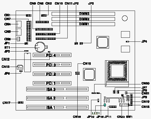
Acer V58 Motherboard
Jumper and Connector Layout

Note - The blackened pin of a jumper represents pin 1.
CPU Jumper Settings
| SW1 Settings | |||||
|---|---|---|---|---|---|
| CPU Freq. | JP14 | JP15 | S1 | S2 | S3 |
| Intel Pentium | |||||
| 90 MHz | 1-3, 2-4 | 3-5, 4-6 | OFF | OFF | OFF |
| 100 MHz | 3-5, 4-6 | 3-5, 4-6 | OFF | OFF | OFF |
| 120 MHz | 1-3, 2-4 | 3-5, 4-6 | ON | OFF | OFF |
| 133 MHz | 3-5, 4-6 | 3-5, 4-6 | ON | OFF | OFF |
| 150 MHz | 1-3, 2-4 | 3-5, 4-6 | ON | ON | OFF |
| 166 MHz | 3-5, 4-6 | 3-5, 4-6 | ON | ON | OFF |
| 200 MHz | 3-5, 4-6 | 3-5, 4-6 | OFF | ON | OFF |
| 233 MHz | 3-5, 4-6 | 3-5, 4-6 | OFF | OFF | OFF |
| For P54C set JP8 3-5,4-6, for P55C(MMX) set JP8 1-3,2-4 then set JP11 to voltage marked on the CPU | |||||
| Cyrix/IBM 6x86 | |||||
| Cyrix/IBM P150+ | 1-3, 2-4 | 3-5, 4-6 | ON | OFF | OFF |
| Cyrix/IBM P166+ | 3-5, 4-6 | 3-5, 4-6 | ON | OFF | OFF |
| Set JP8 1-3,2-4 then set JP11 to voltage marked on the CPU | |||||
| Cyrix M2 | |||||
| Cyrix M2 PR166 | 3-5, 4-6 | 3-5, 4-6 | ON | ON | OFF |
| Cyrix M2 PR180 | 1-3, 2-4 | 3-5, 4-6 | OFF | ON | OFF |
| Cyrix M2 PR200 | 3-5, 4-6 | 3-5, 4-6 | OFF | ON | OFF |
| Set JP8 1-3,2-4 then set JP11 to voltage marked on the CPU | |||||
| AMD K6 | |||||
| PR166 | 3-5, 4-6 | 3-5, 4-6 | 3-5, 4-6 | ON | ON |
| PR200 | 3-5, 4-6 | 3-5, 4-6 | 3-5, 4-6 | ON | OFF |
| PR233 | 3-5, 4-6 | 3-5, 4-6 | 3-5, 4-6 | OFF | OFF |
| Set JP8 1-3,2-4 then set JP11 to voltage marked on the CPU | |||||
Jumper Settings
| Jumper | Setting | Function |
|---|---|---|
| Power Supply Type JP1 JP15 | 1-3,2-4 3-5,4-6 1-2 2-3 | Traditional power supply Resume power supply Traditional power supply Resume power supply |
| JP2 LED Function | 1-2 2-3 | LED for IDE and FDD LED for IDE only |
| JP4 L2 Cache mode | 1-2 2-3 | Interleave / 1+4 mode |
| JP5 BIOS programming voltage | 1-2 2-3 3-4 | 12V for MXIC 5V for SST, ATMEL reserved |
| Hardware monitoring * JP7 JP9 |
1-2 3-4 5-61-2 3-4 |
Vcore 3.2V 2.9V 2.8V V I/O 3.5V 3.3V |
| JP8 CPU Voltage option | 1-3,2-4 3-5,4-6 | Dual voltages (P55C, K6, 6x86L) Single voltage CPU |
| JP11 Core Voltage | 1-2 3-4 5-6 7-8 9-10 11-12 13-14 | 3.3V 2.8V 2.9V 3.2V 3.5V 2.1V Reserved |
| Switch 4 of SW1 Password check | ON OFF | Check password Bypass password |
| JP6 | 2-3 | Reserved |
| JP10 | 2-3 | Reserved |
* When Single-voltage CPU such as P54C is plugged, system hardware monitoring monitors VI/O only and Vcore is ignored
Connector Functions
| Connector | Function |
|---|---|
| CN1 | Serial port 1 |
| CN2 | Serial port 2 |
| CN4 | PS/2 keyboard connector |
| CN5 | PS/2 mouse connector |
| CN6 | Standby power connector |
| CN7 | Power connector |
| CN8 | Printer port |
| CN9 | Diskette drive connector |
| CN10 | IDE connector 2 |
| CN11 | IDE connector 1 |
| CN13 | WOL (Wake On LAN) connector (optional) |
| CN14,16 | Modem ring-in connector (optional) |
| CN17 | USB connector |
| CN18 | Power button connector |
| CN19 | Multifunction connector |
| CN20 | HDD LED connector |
| CN21 | CPU fan connector |
| CN22 | CPU fan and hardware monitoring connector |
| CN30 | CPU Vcore status |
Memory
Module description : 168pin DIMM 3.3V SDRAM Maximum : 256MB