 Acer File Extensions |
Acer V56LA Motherboard
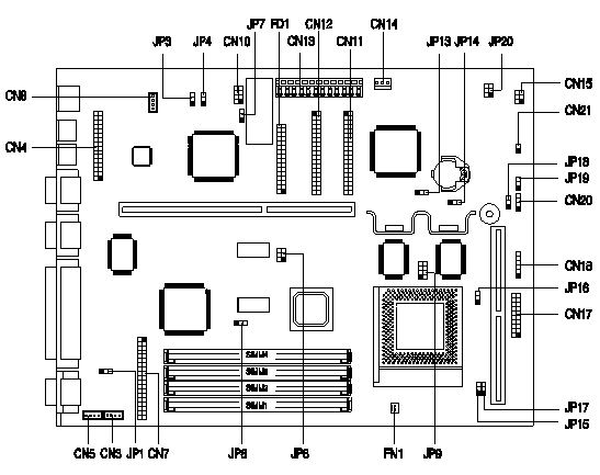
Jumper and Connector Layout

Note - The blackened pin of a jumper represents pin 1.
Specification
The V56LA system has the following features,
- ZIF socket 7 for an Intel Pentium 100/120/133/150/166/200MHz including MMX, Cyrix/IBM 6x86/6x86L and AMD K5/K6.
- Four 72-pin SIMM sockets that support 4/8/16/32-MB 60/70ns fast page mode or EDO SIMMS. Maximum : 128MB
- 256K pipeline-burst second level cache onboard which is not upgradeable.
- 1-MB video memory which is not upgradeable.
- 128K BIOS which is APM and Year 2000 compliant.
- Two Enhanced IDE interfaces supporting a total of four devices including hard drives and CDROMs.
- External ports -
- PS/2 keyboard and mouse ports.
- Two high-speed (NS16C550 compatible) serial ports.
- One ECP/EPP high-speed parallel port.
- VGA port.
- Onboard chipsets -
- Aladdin III system chipset (equivalent to Intel Triton II) with integrated E-IDE and I/O controllers.
- ATI Mach64 VT PCI graphics adapter.
- Plug and Play support.
- Power management features (device standby, global standby).
How do I access my BIOS?
You can access the BIOS by pressing CTRL+ALT+ESC as the system is booting. At the bottom of the second start up screen you should see "To enter setup, press CTRL_ALT_ESC".
Note: If the system displays the Acer Splash Screen, once you hear the beep, you should begin pressing CTRL+ALT+ESC. You may need to press CTRL+ALT+ESC continuously until you access the BIOS setup screen.
CPU Jumper Settings
| CPU Freq, | JP8 | JP9 | JP13 | JP14 | JP15 | JP17 |
|---|---|---|---|---|---|---|
| Intel Pentium | ||||||
| 100 MHz | 3-6 | ON | 1-2 | 1-2 | 1-2 | 1-2 |
| 120 MHz | 2-5 | ON | 1-2 | 1-2 | 1-2 | 2-3 |
| 133 MHz | 3-6 | ON | 1-2 | 1-2 | 1-2 | 2-3 |
| 150 MHz | 2-5 | ON | 1-2 | 1-2 | 2-3 | 2-3 |
| 166 MHz | 3-6 | ON | 1-2 | 1-2 | 2-3 | 2-3 |
| 200MHz | 3-6 | ON | 1-2 | 1-2 | 2-3 | 1-2 |
| Intel Pentium ODP/MMX | ||||||
| 166 MHz | 3-6 | OFF | 1-2 | 1-2 | 2-3 | 2-3 |
| 200 MHz | 3-6 | OFF | 1-2 | 1-2 | 2-3 | 1-2 |
| Cyrix/IBM 6x86 | ||||||
| P120+ | 1-4 | ON | 1-2 | 1-2 | 2-3 | 2-3 |
| P150+ | 2-5 | ON | 1-2 | 1-2 | 2-3 | 2-3 |
| P166+ | 3-6 | ON | 1-2 | 1-2 | 2-3 | 2-3 |
| Cyrix/IBM 6x86L | ||||||
| P120+ | 1-4 | OFF | 1-2 | 1-2 | 2-3 | 2-3 |
| P150+ | 2-5 | OFF | 1-2 | 1-2 | 2-3 | 2-3 |
| P166+ | 3-6 | OFF | 1-2 | 1-2 | 2-3 | 2-3 |
| AMD K5 | ||||||
| PR120 | 2-5 | ON | 1-2 | 1-2 | 1-2 | 1-2 |
| PR133 | 3-6 | ON | 1-2 | 1-2 | 1-2 | 1-2 |
| AMD K6 | ||||||
| PR150 | 2-5 | ON | 1-2 | 1-2 | 1-2 | 2-3 |
| PR166 | 3-6 | ON | 2-3 | 2-3 | 2-3 | 2-3 |
Jumper Settings
| Jumper | Setting | Function |
|---|---|---|
| JP1 Onboard VGA | 1-2 2-3 | Disabled Enabled |
| JP3 BIOS Type | 1-2 2-3 | Acer BIOS OEM BIOS |
| JP4 Password Security | 1-2 2-3 | Check password Bypass password |
| JP6 Second-level Cache | 1-2 2-3 | 256 KB 512 KB |
| JP7 BIOS ROM type | 1-2 2-3 | 1 Mbit 2 Mbit |
| JP16 Cache Operation Mode | 1-2 2-3 | Interleaved burst mode Linear burst mode |
| JP18 LED (CN20) Function | 1-2 2-3 | LED for IDE and FDD LED for IDE only |
| JP19 External Switch Func. (pin 19-20 of CN17) | 1-2 2-3 | Suspend/resume button Reset button |
| JP20 External Switch Func. (CN21) | 1-2 2-3 | UPS enabled UPS disabled |
| JP3001 Reserved | 2-3 | Do not modify this setting |
Connector Functions
| Connector | Function |
|---|---|
| CN7 | ATI media connector |
| CN11 | IDE connector 2 |
| CN12 | IDE connector 1 |
| CN13 | Power connector |
| CN14 | Software shutdown connector |
| CN15 | Hard disk/message LED (hard disk or modem ring-in) |
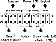
| CN17 | Multifunction connector |
| CN18 | Optional IrDA connector |
| CN20 | FDD/HDD LED connector |
| CN21 | Power switch or 'Appears-off ' switch connector |
| FD1 | Diskette drive connector |
| FN1 | CPU fan connector |
| The multifunction connector CN17 accommodates the front panel connectors for speaker, LEDs, keylock, reset, and turbo. Figure below shows the pin assignments for each connector. |
 |