 Acer File Extensions |
Acer V30-2 Motherboard
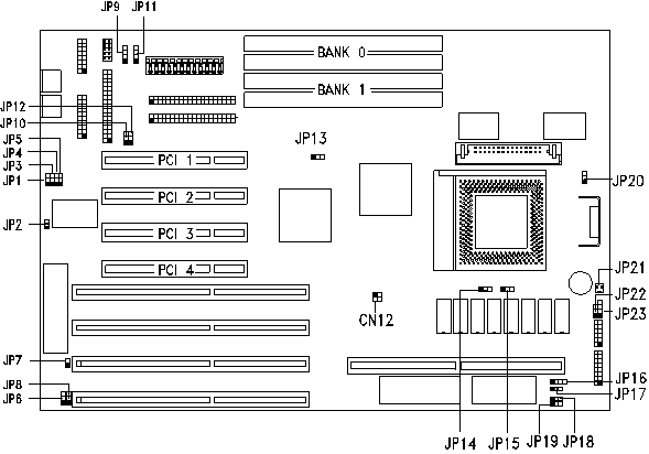
Jumper and Connector Layout

CPU Jumper Settings
| CPU Freq. | JP13 | JP14 | JP15 | CN12 |
|---|---|---|---|---|
| 75 MHz | 1-2 | 1-2 | 1-2 | 1-3, 2-4 |
| 90 MHz | 2-3 | 1-2 | 1-2 | 1-3 |
| 100 MHz | 2-3 | 1-2 | 1-2 | 2-4 |
| 120 MHz | 2-3 | 1-2 | 2-3 | 1-3 |
| 133 MHz | 2-3 | 1-2 | 2-3 | 2-4 |
| 150 MHz | 2-3 | 2-3 | 2-3 | 1-3 |
| 166 MHz | 2-3 | 2-3 | 2-3 | 2-4 |
Jumper Settings
| Jumper | Setting | Function | |
|---|---|---|---|
| JP2 | Open Closed | Normal or standard function Enable ECP function | |
| JP3* | 1-2 2-3 | DRQ3 (for parallel port) DRQ1 (for parallel port) | |
| JP4* | 1-2 2-3 | DACK 3 (for parallel port) DACK 1 (for parallel port) | |
| JP5 | Open Closed | Disable PS/2 mouse (IRQ12) Enable PS/2 mouse (IRQ12) | |
| JP6 | 1-2 2-3 | Enable SMC 665 Disable SMC 665 | |
| JP7 | 1-2 2-3 | Check password Bypass password | |
| JP8 | 1-2 2-3 | Acer BIOS OEM BIOS | |
| JP15 | 1-2 2-3 | Clear RTC Normal | |
| JP20 | 1-2 2-3 | VR or standard CPU (3.3V) VRE CPU (3.6V) | |
| These jumpers must only use the settings shown | |||
| JP1 | Open | ||
| JP9,JP11 | Open | ||
| JP10,JP12 | 1-2 | ||
| JP18 | 1-2 | ||
| JP19 | Open | ||
| JP22 | Closed | ||
Connector Functions
| Connector | Function |
|---|---|
| CN4 | Serial port 2 |
| CN5 | Parallel port |
| CN6 | Serial port 1 |
| CN7 | Diskette drive connector |
| CN9 | Power connector |
| CN10 | IDE connector 2 |
| CN11 | IDE connector 1 |
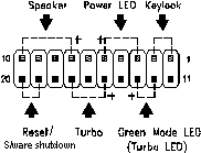
| CN16 | Multifunction connector |
| JP16 | External battery connector |
| JP21 | CPU fan connector |
| JP23 | Hard disk and diskette drive LED connector |
| The multifunction connector CN16 accommodates the front panel connectors for speaker, LEDs, keylock, reset, and turbo. Figure below shows the pin assignments for each connector. |
 |
Memory
Module description : 72pin EDO 70ns Maximum : 128MB