 Acer File Extensions |
Acer M3 Motherboard and CPU Boards
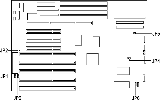
Jumper and Connector Layout

Jumper Settings
| Jumper | Setting | Function |
|---|---|---|
| JP1 Password | 1-2 2-3 | Check password Bypass password |
| JP2Reset button | Open Closed | Reset button disabled Reset button enabled |
| JP3 BIOS type | 1-2 2-3 | Acer BIOS OEM BIOS |
| JP4 RTC NVRAM | 1-2 2-3 | 128 bytes or 256 bytes 4KB, reserved |
| JP6 Sound Output | 1-2 2-3 | Buzzer Speaker |
Connector Functions
| Connector | Function |
|---|---|
| J4 | COM2 connector |
| J5 | COM1 connector |
| J6 (PRN) | Parallel connector |
| J8 | Power connector |
| J9 | IDE connector |
| J10 | Diskette drive connector |
| J16 | EIDE1 connector * |
| J17 | EIDE2 connector * |
| J15 | SCSI connector * |
| J19 | Power LED connector |
| J20 | HDD LED connector |
* A SCSI or EIDE version of the board was available. The SCSI version had no EIDE connectors and vice-versa.
Memory
Memory Module : 72pin Parity 70ns Maximum : 128MB
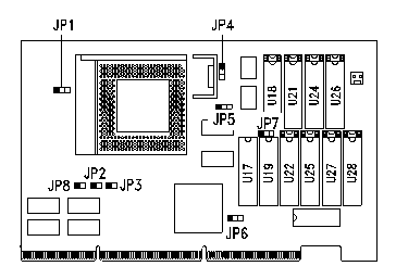
ALI Pentium CPU Board 3.3v (PCB 94414-1)
 |
|
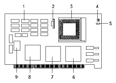
Pentium CPU Board 3.3v (PCB 94323-1)
 |
Key to diagram 1 Second-level cache 6 LBX | |||||||||