Acer File Extensions |
Acer 6400 Motherboard
Jumper and Connector Layout
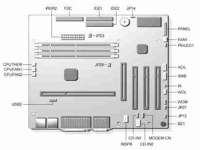
Jumper Settings
| Jumper | Setting | Function |
|---|---|---|
| JP12 - Sound | 1-2 2-3 | Enabled (default) Disabled |
| JP14 - CMOS Setting | 1-2 2-3 | Normal Operation (default) Clear CMOS |
| JP27 - PC Beep Output | 1-2 2-3 | Onboard Buzzer (default) Line-out |
| JP23 | N/A | N/A |
| JP29 | N/A | N/A |
Connector Functions
| Connector | Function |
|---|---|
| PWR2 | ATX power connector |
| USB2 | USB connector |
| FDC | Floppy drive connector |
| IDE1 | IDE1 primary channel |
| IDE2 | IDE2 secondary channel |
| CPUFAN1 | 3-pin CPU fan connector |
| CPUFAN2 | 2-pin CPU fan connector |
| CPUTher | 2-pin CPU Thermal detector connector |
| FAN1 | Fan connector (reserved) |
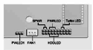
| Panel | Front panel (multifunction) connector |
| CD-in 1 and 2 | CD-audio connector (Do not use both connectors at the same time) |
| INSPk | Internal speaker connector (reserved) |
| Modem-cn | Mono-in (pin 1-2) and Mic-out (Pin 3-4) |
| BZ1 | Onboard buzzer |
| WOM | Wake-on-Modem connector (reserved) |
| WOL | Wake-on-LAN connector |
| SMB | SMBus connector |
| IA | Intrusion alarm connector |
| AOL | Alert-on-LAN connector |
| SPWR* | Power switch connector |
| PWRLED* | N/A |
| Turbo LED* | Turbo LED connector |
| HDD LED* | Hard disk LED connector |
| PWLED1 | Power LED connector |
* Located in the Panel connector
Memory Upgrade
The system is upgradable to a maximum of 256MB via two 168-pin DIMM sockets on board. These DIMM sockets accept DRAMs with 8, 32, 64, and 128MB capacities, 60ns (nanoseconds) or less access time, and ECC, PC100Mhz.
BIOS
How do I enter the BIOS Setup Utility?
You can access the BIOS Setup Utility by pressing CTRL+ALT+ESC as the system is booting. At the bottom of the second start up screen you should see "To enter setup, press CTRL_ALT_ESC".
Note: If the system displays the Acer Splash Screen, once you hear the beep, you should begin pressing CTRL+ALT+ESC. You may need to press CTRL+ALT+ESC continuously until you access the BIOS setup screen.