Acer File Extensions |
Acer 6200 Motherboard
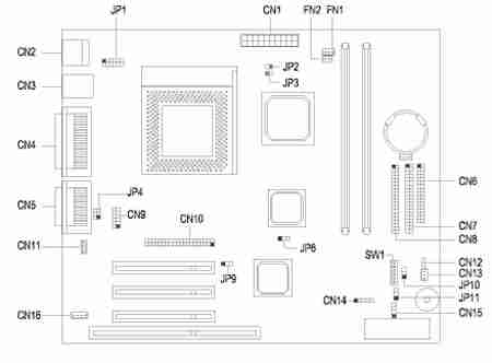
Jumper and Connector Layout
- Processor: Intel Celeron 333MHz, 366MHz, 400MHZ, or 466MHz
- Cache: 128K
- Memory: 32 or 64MB Expandable to 256 MB
- BIOS: Acer Version 3.2
- Power Supply: 145W TG-1458-C
- Audio: PCI ESS Solo 1 Sound System
- Speakers: Altec Lansing External speakers included
- Video: ATI 3D Rage Pro Turbo 2x AGP 8MB video memory or ATI Xpert 98 2x AGP 8MB video memory
- Storage:
- One 3.5" 1.44MB diskette
- 40x maximum CD-ROM or 4x DVD
- 3GB, 4.3GB, 6.4GB or 8.4GB Hard Disk Drive
- Case: Aspire Micro-Minitower
- Modem (selected models): 56Kbps modem (V.90 ITU and K56Flex standards)
- Ports: 5 USB ports (2 open) Parallel printer port 1 Serial and 1 game port
Jumper Settings
| Jumper | Setting | Function |
|---|---|---|
| JP5 - VGA Int. (Rage 128 VR) | 1-2* 2-3 | Disabled Enabled |
| JP6 - VGA Int. (RagePro Turbo) | 1-2* 2-3 | Disabled Enabled |
| SW1-5 - Password | On* Off | Bypass password Check password |
| SW1-6 - BIOS | On* Off | OEM Acer |
| SW1 Settings (for FSB = 66MHz) | |||||
|---|---|---|---|---|---|
| Processor Frequency | 1 | 2 | 3 | 4 | |
| 300A | On | Off | On | Off | |
| 333 | On | On | Off | Off | |
| 366 | On | Off | Off | Off | |
| 400 | Off | On | On | On | |
| 433 | Off | Off | On | On | |
| 466 | On | Off | Off | On | |
| SW1 Settings (for FSB = 100MHz) | |||||
| Processor Frequency | 1 | 2 | 3 | 4 | |
| 400 | On | On | On | Off | |
| 450 | On | Off | On | Off | |
Connector Functions
| Connector | Function |
|---|---|
| CN1 | Power connector |
| CN2 | USB port connector |
| CN3 | PS/2 to USB daughterboard connector |
| CN4 | Parallel port connector, Com port connector, VGA port connector, Serial port connector |
| CN5 | Audio line-in / line-out port, Microphone-in port, Midi port |
| CN6 | Diskette drive connector |
| CN7 | IDE 1 connector |
| CN8 | IDE 2 connector |
| CN9 | COM 2 |
| CN11 | FAX-Modem-in |
| CN12 | Power switch |
| CN13 | Wake On LAN connector |
| CN14 | Modem Ring-in connector |
| CN15 | IDE LED connector |
| CN16 | CD-in |
| JP1 | USB connector |
| JP3 | Processor thermal sensor connector |
| JP9 | Reset switch |
| JP10 | Turbo LED connector |
| JP11 | Power LED connector |
BIOS
How do I enter the BIOS Setup Utility?
You can access the BIOS Setup Utility by pressing CTRL+ALT+ESC as the system is booting. At the bottom of the second start up screen you should see "To enter setup, press CTRL_ALT_ESC".
Note: If the system displays the Acer Splash Screen, once you hear the beep, you should begin pressing CTRL+ALT+ESC. You may need to press CTRL+ALT+ESC continuously until you access the BIOS setup screen.