Acer File Extensions |
Acer 2100 Motherboard
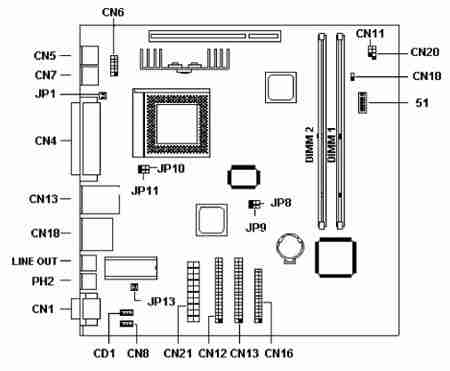
Jumper and Connector Layout
Jumper Settings
| Jumper | Setting | Function |
|---|---|---|
| JP12 - Vcore Voltage | 1-2 2-3 * | 2.8v 2.2v |
| JP8, JP9 - SDRAM, PCI | 1-2, 1-2 2-3, 1-2 * 1-2, 2-3 2-3, 2-3 | 60MHz CPU, SDRAM - 30MHz PCI 66MHz CPU, SDRAM - 33MHz PCI 75MHz CPU, SDRAM - 30MHz PCI 83MHz CPU, SDRAM - 33MHz PCI |
| JP10 - CPU Type | 1-2 2-3 * | AMD K6-300 AMD K6-333 and AMD K6-366 |
| JP11 - Voltage Type | 1-2 2-3 | K6-300 K6-333 and K6-366 |
| (For CY2273 CLK Generator) | ||||
|---|---|---|---|---|
| SW2 | SW1 | CPU, SDRAM | PCI | |
| On | On | 60MHz | 30MHz | |
| On | Off | 66MHz | 33MHz | |
| Off | On | 75MHz | 30MHz | |
| On | Off | 83MHz | 33MHz | |
| (For ICS9148 CLK Generator) | ||||
| SW3 | SW2 | SW1 | CPU, SDRAM | PCI |
| Off | Off | On | 60MHz | 30MHz |
| *Off | Off | Off | 66MHz | 33MHz |
| On | On | Off | 75MHz | 30MHz |
| On | Off | On | 83MHz | 33MHz |
| (Core/Bus CLK Rate) | ||||
| SW6 | SW5 | SW4 | P55C | PCI |
| * Off | Off | Of | 3.5 | 30MHz |
| Off | Off | On | 2 | 33MHz |
| Off | On | On | 2.5 | 30MHz |
| Off | On | Off | 3 | 33MHz |
| *On | Off | On | ||
| On | On | Off | ||
| On | Off | Off | ||
Connector Functions
| Connector | Function |
|---|---|
| CD1 | CD-In |
| PH2 | Speaker Out |
| JP13 | Fan Connector or Power Supply |
| CN10 | Power Button |
| CN20 | Active LED |
| CN11 | Power LED - Pin1 (Green), Pin2 (Orange), Pin3 (Black) |
Memory Upgrade
The system memory is upgradable to a maximum of 256MB via two 168-pin DIMM sockets onboard.These DIMM sockets accept 128MB, 3.3V Synchronous DRAM modules in capacities of 32-, 64-, and 128-MB.
BIOS
How do I enter the BIOS Setup Utility?
You can access the BIOS Setup Utility by pressing CTRL+ALT+ESC as the system is booting. At the bottom of the second start up screen you should see "To enter setup, press CTRL_ALT_ESC".
Note: If the system displays the Acer Splash Screen, once you hear the beep, you should begin pressing CTRL+ALT+ESC.You may need to press CTRL+ALT+ESC continuously until you access the BIOS setup screen.